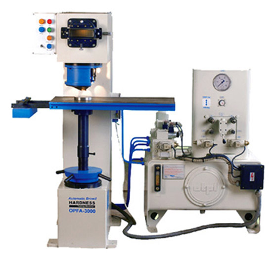
Automatic Optical Brinell Hardness Testers
( Model : OPFA-3000, OPFA-3000-PC )
We are Manufacturer, Supplier, Exporter of Automatic Optical Brinell Hardness Testers and our set up is situated in Sangli, Maharashtra, India. We provide our whole range to ALL OVER THE WORLD, but majorly we serve our customers from countries like Middle East, Saudi Arabia, Africa, USA, Oman, Dubai Abu Dhabi, UAE, Kenya, Ethiopia, Uganda, Malaysia & Indonesia.
 Fine Spavy Associates & Engineers Pvt. Ltd. (Unit-I)
Features :
- The machine has a robust, C-type load frame & has been designed for production testing of cast or forged
- components like leaf springs, cam shafts, etc. for Brinell hardness value. This machine is suitable for foundries,
engineering industry on production line.
- Since most of the operations are fast and automatic, the test speed is high with less operator fatigue.
- The cycle time (except loading / unloading) is about 12 seconds per test.
- Load stages � 750 kgf and 3000 kgf.
- Optical measuring equipment with 14 X magnification.
- Job loading / unloading, push button operation, pushing cycle start, de-clamp buttons are only manual operations &
rest all is automatic.
- A push button is pressed for cycle start & hydraulic operations. After cycle time, impression is visible on screen,
which (Diameter) is to be measured with the help of microscope of least count 0.01mm.
- Computerized model is available. Computerized model has built in CCD and suitable advanced software. Hardness
will be displayed on computer monitor automatically. Results printout can be taken.
- Accuracy conforming to IS:2281.

Automatic Optical Brinell Hardness Testers
( Model : OPFA-3000, OPFA-3000-PC )
Technical Specification for Automatic Optical Brinell Hardness Testing Machines - Model : OPFA-3000A - 3000
| SPECIFICATION |
Load stages - 750 kg and 3000 kg.
Load stage of 500 kg and / or 1000 kg can be provided at additional cost. |
- |
Machine frame (C type)
a) Depth of throat
b) Max. Distance between supporting table and penetrator
c) Size of supporting table with fixing slots |
- 200 mm
- 360 mm
- 260 x 400 mm |
Optical Measuring Equipment with image projection on front screen
a) Magnification
b) Least count of measurement
|
- 14 X
- 0.01 mm |
Hydraulic Systems
a) Maximum working pressure
b) Stroke of clamping piston
c) Stroke of loading piston |
- 70 bar
- 20 mm
- 18 mm |
Drive - Electro hydraulically operated suitable for
a) Supply
b) Power pack |
- 3 Ph. 440 V, 50 C/Sec. A.C.
- 1 HP |
Overall dimensions (width x Depth x Height)
a) Machine
b) Power Pack |
- 410 x 700 x 1350 (Aprox)
- 600 x 500 x 975 (Aprox) |
Net weight
a) Machine
b) Power pack
|
- 450 kg (Aprox)
- 150 kg (Aprox) |
| SCOPE OF SUPPLY |
| Machine as specified above |
- 1 No |
| Power pack |
- 1 No |
| Standard Accessories as per below - |
|
a) Main screw extension (for 0 - 130 mm)
b) Main screw extension (for 125 - 255 mm)
c) Test table with slots for clamping
d) 100 mm Vee table for round jobs
e) Ball holder 5 mm
f) Ball holder 10 mm
g) Test Block HB 5 / 750
h) Test Block HB 10 / 3000
i) Instruction manual
j) Set of Spanners
|
- 1 No
- 1 No
- 1 No
- 1 No
- 1 No
- 1 No
- 1 No
- 1 No
- 1 No
- 1 No |
Operation of the Machine :
1. Initial Settings
a) Depending on height of job, select a suitable screw extension piece and fix it to the main screw.
b) Depending on shape of job select a suitable support flat i.e. Vee table for round jobs and flat table for jobs with flat bottom. Fix this at the screw / extension top.
c) Position the load selector lever to the required test load i.e. 750 kg or 3000 kg.
e) Confirm that required ball indentor dia 5mm or 10 mm is fixed.
f) Position the job on the table and adjust the screw height such that the test face of job is about 5 mm below the clamping cone bottom face. Now the machine is ready for production testing.
2. Test Cycle :
a) Start machine by ON push button. The clamping piston goes to bottom position and loading piston with indentor goes to the top position and the indentor shifts to indexed (fitted)
position.
b) Push the cycle start button. The bottom piston moves up and the job is clamped against the clamping cone with a force of 500 kg. Then the loading piston moves down.
The indentor shifts to its vertical position and the set load is applied on the test piece a light signal is provided which glows when the load is applied. The applied load is kept constant for a pre set time. Then the loading piston moves up and the indentor is indexed so that the impression is visible on the screen. Measure the impression by the micrometer.
c) Push the de-clamp button.
d) Unload the job and machine is ready for next test.
3. Thus :
a) Job loading / unloading
b) Impression / measurement
c) Pushing cycle start
d) De-clamp buttons
Are only manual operations and rest all is automatic.
The machine is designed for continuous operation in the environments of foundry / forge shop, etc.
 Fine Spavy Associates & Engineers Pvt. Ltd. (Unit-I)
 Automatic Optical Brinell Hardness Testers
( Model : OPFA-3000, OPFA-3000-PC )